Centrifugal Pump Sizing & Fluid Dynamics Engine
Deterministic calculations for Total Dynamic Head (TDH), H-Q pump curves, Colebrook-White friction, and NPSHa cavitation verification with continuous IAPWS-IF97 steam formulations.
Boiler Specifications
Steam generation rate and operating pressure
Engineering Report
Generate a printable PDF report with all inputs, equations, and results
Centrifugal Pump Sizing, System Curve Analysis & Fluid Hydraulics
Accurate hydrodynamic sizing bridges fundamental fluid mechanics with daily plant commissioning. Explore governing formulations for Total Dynamic Head (TDH), affinity laws, Colebrook-White pipe friction, and NPSHa cavitation margins per ASME BPVC and API 610.
Dynamic H-Q Operating Point
Computes parabolic system head resistance (H_sys = H_stat + k · Q²), pump characteristic droop curves, and evaluates VFD frequency modulation using affinity laws.
Darcy-Weisbach & Reynolds Flow
Solves continuous boundary layer shear friction across turbulent flow regimes (Re > 4,000) using exact Colebrook-White formulations rather than empirical tables.
NPSH Cavitation Safeguards
Protects multi-stage rotodynamic machinery from vapor bubble nucleation, high-velocity micro-jet erosion, and acoustic suction recirculation trip conditions.
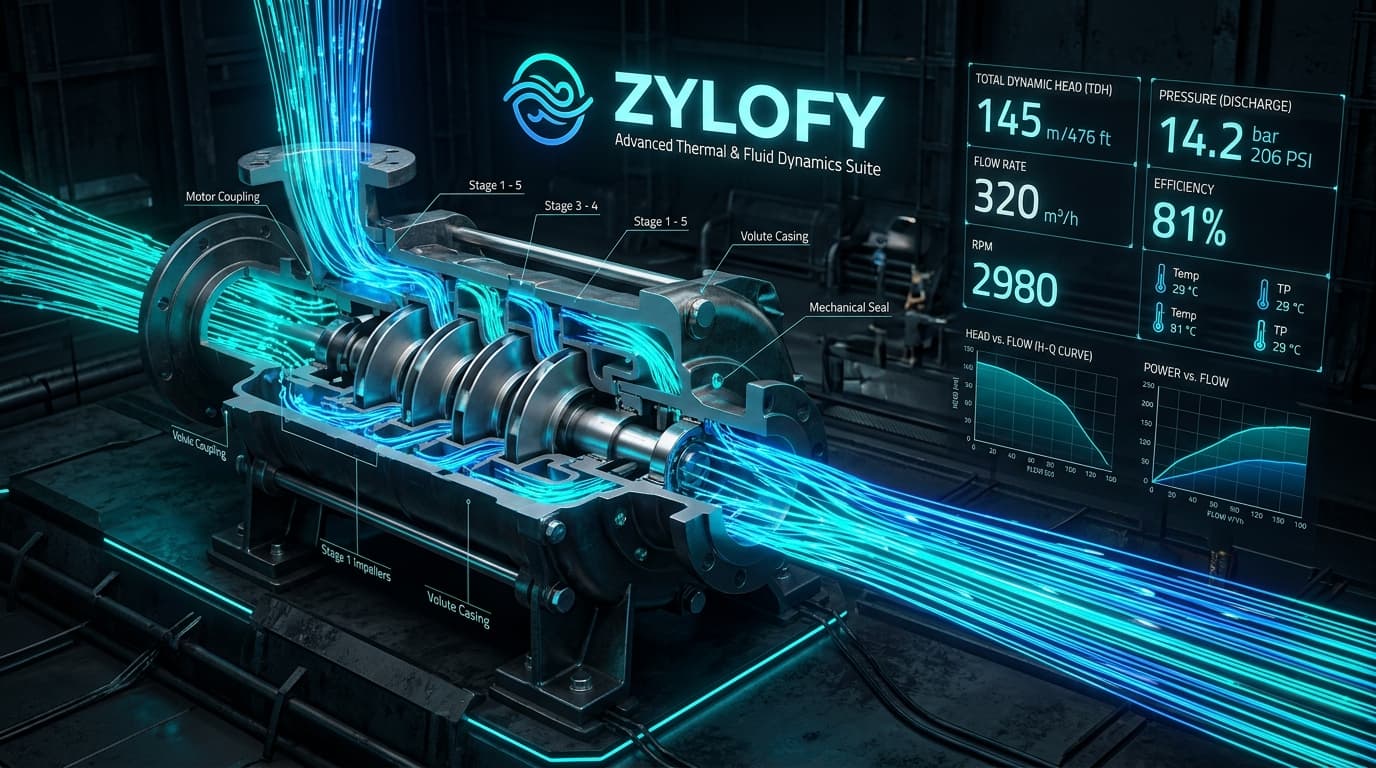
Figure 1: High-Pressure Multistage Centrifugal Process Circuit with Dynamic Flow Telemetry, Elevated Suction Storage, and API 610 Seal Loops.
1. Centrifugal Pump Performance & System Head Intersection
Read TDH Sizing Guide →A centrifugal pump does not operate at an arbitrary flow rate; rather, it operates exclusively at the intersection of its Manufacturer Head-Flow Curve (H-Q) and the Piping System Head Curve.
Static head remains independent of flow rate, representing physical elevation difference and vessel differential pressure. Dynamic friction losses grow with the square of velocity, dictating a parabolic rise in required head.
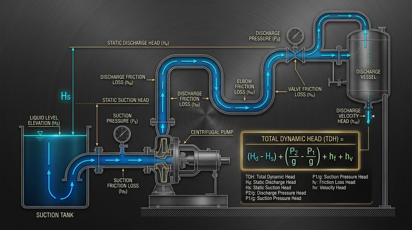
Figure 2: Parabolic System Head Curve intersecting Pump Performance Curve at the Best Efficiency Point (BEP).
2. Darcy-Weisbach Friction Modeling & Reynolds Regimes
Read Friction Factor Guide →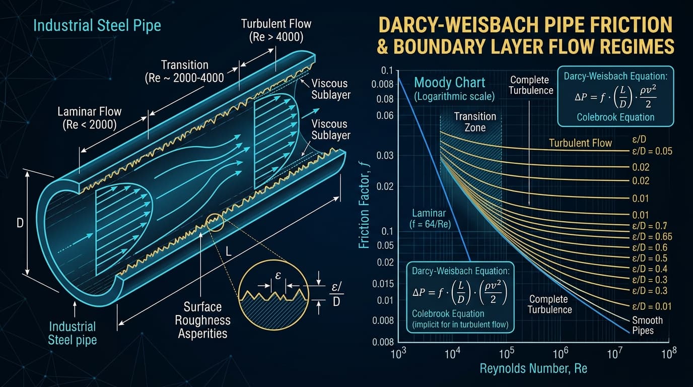
Figure 3: Hydrodynamic boundary layer velocity distribution, viscous sublayer, and Colebrook friction parameters.
Empirical approximations introduce up to 25% sizing errors when operating outside narrow temperature ranges. Zylofy applies the rigorous Darcy-Weisbach equation in conjunction with the implicit Colebrook-White relationship:
Flow regime transitions from laminar (Re < 2,300) where friction factor is independent of surface roughness (f = 64 / Re), to fully rough turbulent flow where the viscous sublayer is submerged within wall asperities (ε).
3. Cavitation Dynamics: NPSH Available vs. Required
Read Cavitation Handbook →Cavitation occurs when fluid static pressure drops below saturation vapor pressure (P_vapor) at the local temperature, causing instantaneous vaporization into micro-bubbles. As these bubbles travel into higher pressure zones of the impeller blade, they implode violently within nanoseconds.
Imploding bubbles generate supersonic micro-jets exceeding 1,000 m/s with localized shock pressures topping 10,000 bar, pitting hardened stainless impellers and inflicting acoustic vibration damage.
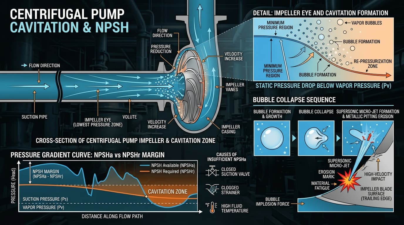
Figure 4: Impeller vane pressure gradient, vapor bubble nucleation, and localized micro-jet shockwave implosion.
Frequently Asked Technical Questions (FAQ)
Explore the Complete Zylofy Technical Library
Delve into all 8 in-depth engineering monographs on pump affinity scaling, piping friction factors, and cavitation diagnostics.